 |
|
 |
 |
 |
 |
 |
 |
 |
 |
 |
 |
 |
 |
 |
 |
 |
 |
 |
 |
 |
 |
 |
 |
 |
 |
 |
 |
 |
 |
 |
 |
 |
 |
 |
 |
 |
 |
 |
 |
 |
 |
 |
 |
 |
 |
 |
 |
 |
 |
 |
 |
 |
 |
 |
 |
 |
 |
 |
 |
 |
 |
 |
 |
 |
 |
 |
 |
 |
 |
 |
 |
 |
 |
 |
 |
 |
 |
 |
 |
 |
 |
 |
 |
 |
 |
|
|
|
|
|
DMS Chassis # 54
|
|
|
These pages will document my own Dick Mann Specialties DMS TT500 YAMAHA version 1 and its rebuild. I am very happy that I never sold this bike while it sat so long taken apart. I had many opportunities to sell it and had some hard times when I thought about selling it since about 1985, but it sat safely put away in boxes .
As my rebuild commences there will be some “non-conforming” additions to it. Although my new “Modern Mann” version 1 I am building will employ inverted forks, disc brakes and a pumper carb (big time NO NO in the vintage world) I am doing the build so that it will remain true to the period and spirit and still employ my original 1979 YZ400 front end, full floating rear drum brake and period acceptable carburetor. I will also be sure to keep everything possible intact to take on the basic stock TT parts that Dick Mann had intended with this kit. Any changes and improvements that I do to the chassis will be thought out to try to duplicate the original style and craftsmanship that Dick Mann and his sub contractors would employ, I understand there were several contributors from the information I have gathered through the years. I hope to speak with Dick Mann in the near future for more details of this chassis and the craftsmen involved. All of them are legendary in their accomplishments of the era and most are now long retired.
|
|
|
Links to sub sections
|
|
|
|
- Hubs and wheels
- Triple clamps
- Forks
- Shocks
- Brakes
- Intake
- Exhaust
- Drive
- Controls & foot pegs
- Tank, seat, body parts
- Engine
|
|
|
|
|
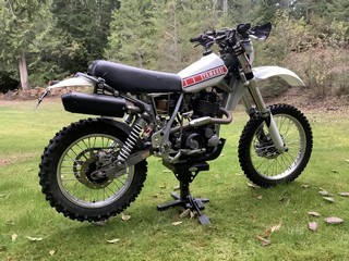
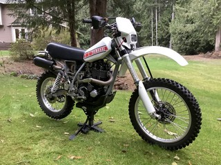
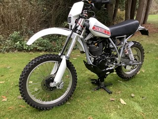
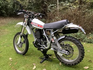
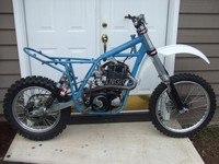
Here’s my DMS #54, after 300 miles of riding it’s now apart for Paint, Polish, Plating & finish work. Have had lot’s of fun riding it as is, what a HOOT to ride this thing!
|
|
|
|
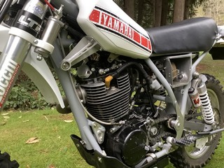
What’s left of the original 1976 Yamaha TT500? Not much. The glorious long stroke, 2 valve GENUINE THUMPER engine, the seat and rear fender is all that remains. Everything else is essentially hand made, many Honda CR & XR parts are adapted for this purpose made machine, everywhere you look leads to more custom hand made goodness!
|
|
|
|
Click on thumbnail to view large image
|
|
|
 |
|
|
 |
|
 |
|
|
|
|
|
|
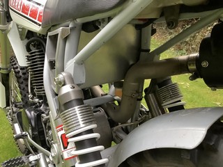
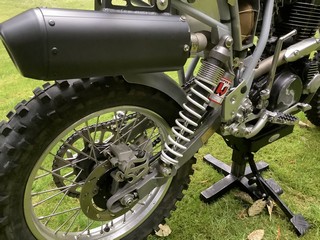
Honda CR hubs & Nissin brakes, BRP billet clamps for CR spec. forks. Custom made Marzocchi works 45 mm closed chamber forks with DLC coating, sub tanks are currently fitted. The shocks are WP twins I totally reconfigured for this application, at least 40 hrs time in machining & set-up. Oh yeah, it’s completely road legal too!
|
|
|
 |
|
|
 |
|
|
 |
|
|
|
|
|
|
|
|
|
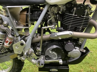
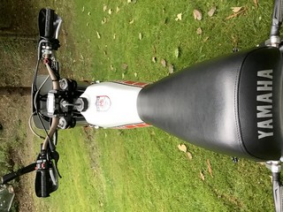
Head pipe is part of the original DMS frame kit. I made the complete mid pipe and silencer S/A of my own design using an MX can, its essentially hollow inside, noise level is adjustable, free flowing even when quiet! Hand made aluminum monocoque design air box holds XR filter & intake boot, feeds a custom KeiHin FCR 39 Racing carb. Hand made brake pedal system & M/cyl. mounts, IMS pro pegs are adapted to the DMS peg mounts
|
|
 |
|
|
 |
|
|
|
 |
|
|
|
|
|
|
|
|
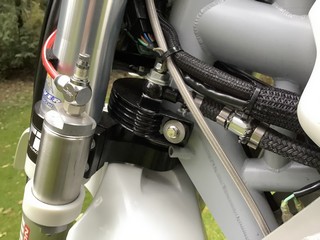
A Honda XR250R oil cooler has been fitted with a side-stream return circuit, the oil temps are usually too cool under normal usage up to 80 F degree air temp, not until above 80 F does the oil come up to normal temps. Hydraulic clutch has also been added.
|
|
|
 |
|
|
 |
|
|
 |
|
|
|
|
|
|
|
|
|
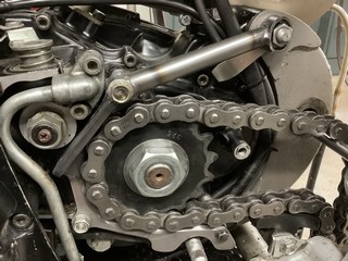
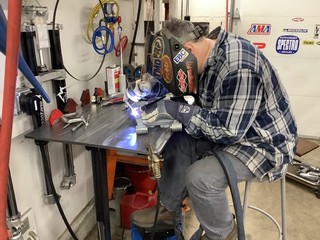
A real, effective case guard using 4130 was made that may actually works as intended. I had an aluminum 3 bolt case guard that many offer and promptly sucked a rock into the C/S sproket, destroying the cases. Don’t ever think those actually work when needed. On the right is Jeff, he’s a certified aircraft welder plus 10 years at Art Morrison chassis. I do all his suspension work, he does all my welding, perfect! Thanks Jeff!
|
|
|
|
The Frame rebuild
|
|
|
|
Click on thumbnail to view large image
|
|
|
|
 |
|
|
|
 |
|
 |
|
|
|
|
|
 |
|
|
|
|
|
|
|
|
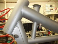
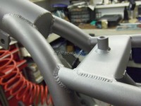
The right side of the headstock. Nice beads, looking inside the oil filler tube and inside the headstock you can see the full penetration of the precision TIG welds all laid by hand. The oil pipe connections are brazed in, very thin wall tube is used for these connections.
|
|
|
|
|
|
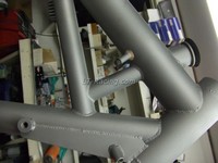
Above, You can barely make out the production number on the headstock.
|
|
|
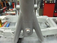
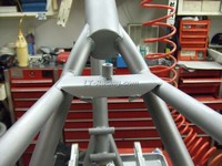
The front downtube meets the lower cradle here.
|
|
|
|
|
|
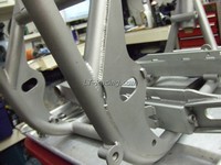
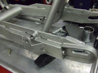
The right side swing arm plate.
|
|
|
|
|
|
|
|
|
|
 |
|
|
|
|
 |
|
|
 |
|
|
|
|
|
|
|
|
|
|
 |
|
|
|
|
|
|
|
|
|
|
|
|
The rear fuel tank mount and seat plate.
|
|
|
A partial shot of the swingarm.
|
|
|
|
|
|
|
|
This is probably my favorite joint, where the rear cradle tubes are birds mouthed into the rear backbone. The picture just doesn't do it justice like seeing it.
|
|
|
|
|
|
|
|
|
|
 |
|
|
|
|
 |
|
|
|
|
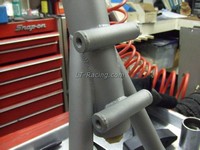
The front lower engine mounts. Note the thin wall crosstube with the welded in end caps. Most every joint is very long to spread the load over a wide area, necessary with this type of construction with 4130 thin wall tube.
|
|
|
|
|
|
|
|
|
|
|
|
 |
|
|
|
|
|
|
|
 |
|
|
|
|
|
|
|
Later style Engine cradle/swing arm pivot (pre-modified) used with later style swing arm. The pivot is 3/4” (19 mm) diameter. Big even by today’s standards.
|
|
|
|
|
|
|
Another view from the engine side. The boxed in section joins at the S/A cross tube.
|
|
|
|
|
|
|
|
|
|
|
|
|
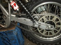
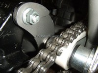
Inboard S/A pivot collars machined from 303 stainless. The modified bearing pin presses into the collar and the large flange spreads the load.
|
|
|
|
|
 |
|
|
|
|
|
|
|
 |
|
|
|
|
|
|
|
|
|
|
This is after the cradle was boxed in and strengthened by me. Engine mount side plates help spread the load and vibration out.
|
|
|
|
|
|
|
|
|
|
|
|
 |
|
|
|
|
|
|
|
 |
|
|
|
|
|
|
|
|
|
|
The stronger engine cradle and S/A pivot will keep things in check with the updated S/A. Now she has a solid set of hips to keep that ass in line!
|
|
|
|
|
|
|
|
A thrust washer on opposite side of bearing pin with new spacers machined from 6061 are larger 1.5” (38 mm) diameter to 1 3/4” (44.5 mm) at the outboard side plate. More load spreading.
|
|
|
|
|
|
|
|
|
|
|
|
|
|
|
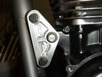
With the stronger cradle, the front and upper motor mount plates begin to take shape.
|
|
|
|
|
 |
|
|
|
|
|
|
|
|
|
|
|
|
Preliminary layout. Rear wheel travel of 8.9” (226.4 mm) Fork travel will be shortened 3/4” (19 mm) to yeild 10.5” (266.7 mm). Wheelbase 58” (1473 mm) with axle forward.
|
|
|
 |
|
|
|
|
|
|
|
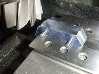
Front motor mounts roughed out of 1/2 inch (12.7 mm) 6061 plate, the web is .125” (3.2 mm) thick. .187” (4.8 mm) flat plate was used originally.
|
|
|
|
|
|
|
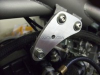
The upper mount roughed out, since the engine grows in height when it is hot, there must be some slip accounted for in the mount design. Original was .125” (3.0 mm) thick, new one is .250” (6.3 mm).
|
|
|
|